Grow Your Digital Plant
Abstract
In this tutorial article, the author shows how to make a complete plant using the Maya 3D® application, and Photoshop®. The process is designed to maintain maximum flexibility, allowing for the not uncommon case of the customer’s request for modifications.
– Ed. Note: A complete presentation of all images and workflow are organized in a supplementary PDF linked here.
When dealing with several projects at the same time, we may not have the luxury to choose the best way of completing the projects. We may have to find the most efficient way to finalize the projects on time. To deal with clients’ feedback and additional imaging requests efficiently, three-dimensional (3D) computer graphics software can be advantageous.
The general workflow in such software includes modeling, texturing, lighting, rigging (for animation), rendering, and compositing. The advantage of using 3D computer graphics software for scientific illustrations comes when each of these workflow steps is connected smoothly, making it easy to respond to clients’ feedback.
In this article, I describe how I created a quinoa plant illustration using Autodesk Maya®. If you are not used to using Maya, then following this tutorial will be a practical exercise and provide an alternative way for you to create your next plant illustration. Other 3D packages have a similar workflow.
The final version of my quinoa plant illustration is presented in Figure 1. I used Maya® software for modeling, Mental Ray for rendering and Adobe Photoshop® for compositing. However, I will explain how to use an alternate renderer, Arnold, for texturing and rendering to optimize the process on the current Maya version. To begin, I used NURBS/poly modeling. NURBS modeling is similar in concept to Abobe Illustrator’s mathematical descriptions of curved lines, but in the 3rd dimension. Polygon modeling converts the NURBS curves into a simpler format of points (vertex) and straight edges, creating triangles and rectangles for export and rendering. For the texturing, I used a reference photo of a quinoa plant leaf.
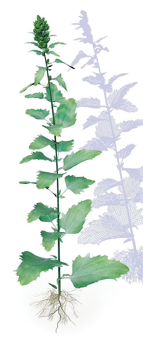
Figure 1: Quinoa plant render, with the 3D frame- work in the background.
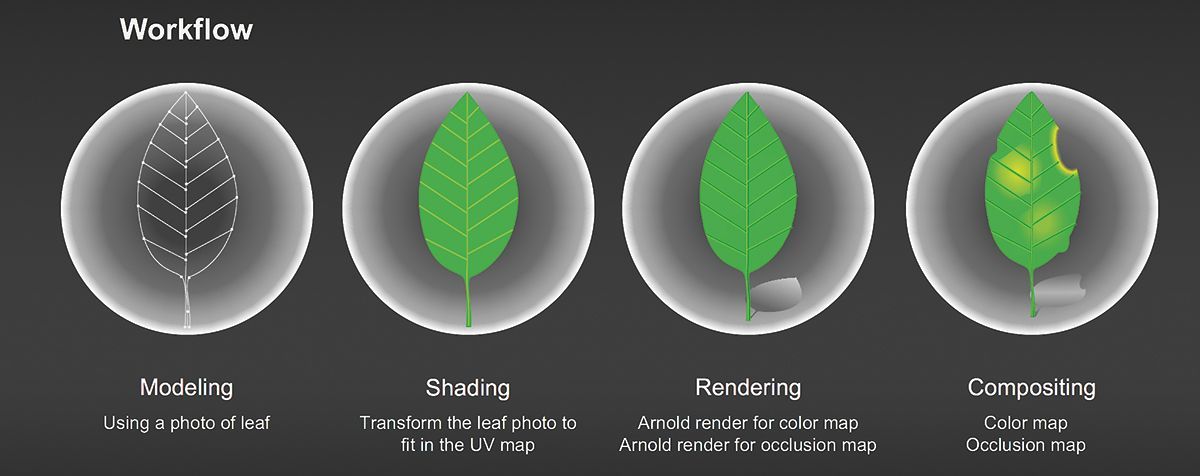
3D Quinoa PlantWorkflow diagram for the project.
MODELING
Leaf Modeling
1. Take photos of the plant using your smartphone or digital camera. This process does not require a high-resolution camera, but you need to place the plant’s leaf on a flat surface to make a photo for the modeling.
2.
Crop the photo to the leaf and place into a square shape. Save the cropped photo (leaf_t.jpg).
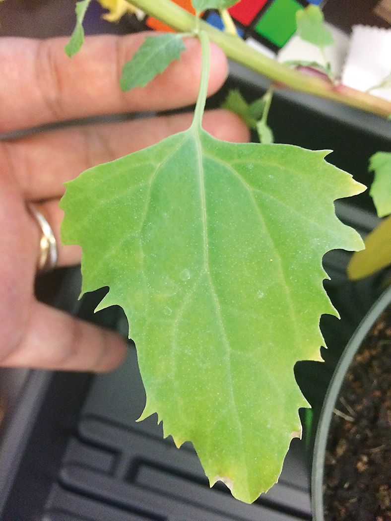
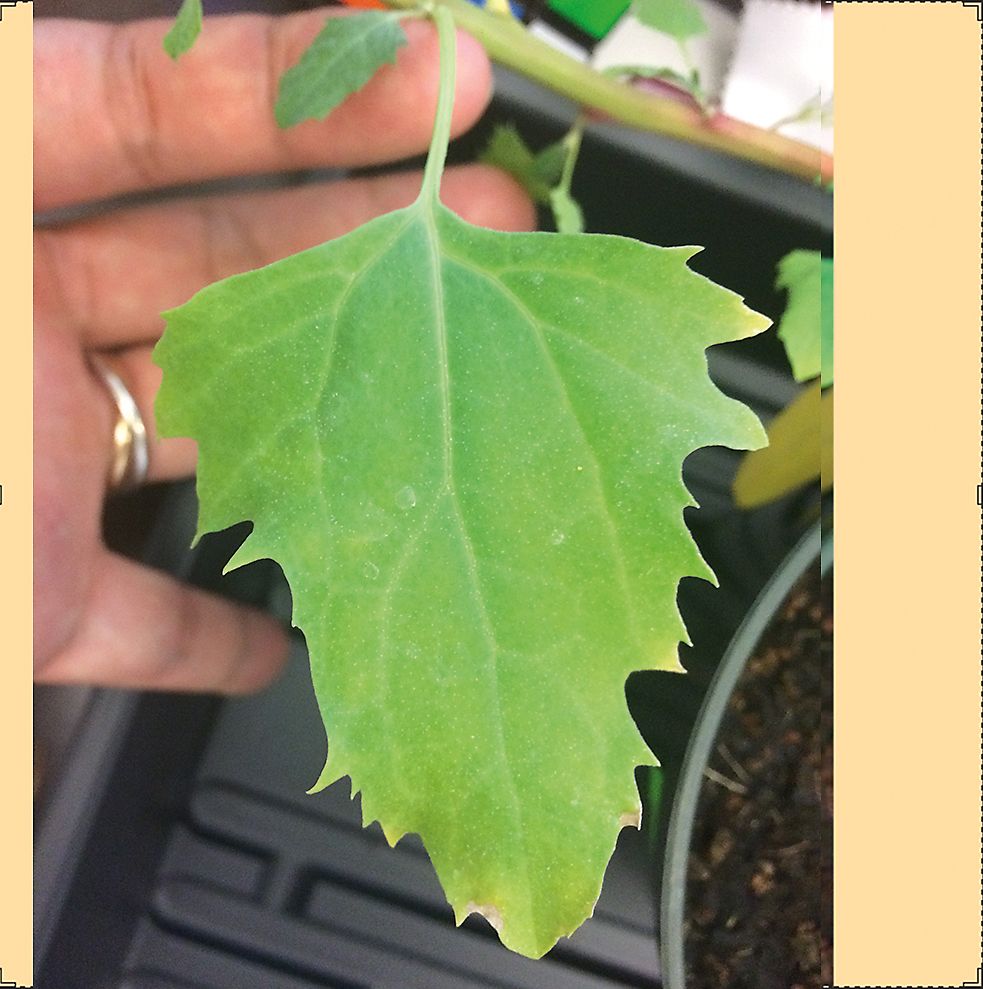
Figure 2: Original photo is formated into a square for use as a UV texture and template for 3D objects.
3. Import the cropped photo into Maya top-view camera. This will be used as a template for the leaf model.
4. If the image size is too large, scale down the photo.
5.
Click the pencil curve tool to draw a curve over the imported image, using your mouse, by following the shape of the leaf.
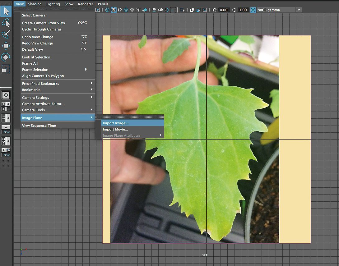
Photo is placed in the work area as a template to draw an outline object.
6. Select the first and last control vertex to close the curve and then rearrange each control vertex to minimize the number of control vertexes while maintaining the accuracy of the shape.
7. Draw additional curves following the leaf veins. All of the control vertexes and curves should be connected through “snapping” to the leaf curve edges.
8. Select all curves and create a “polygon planar” (Fig. 3).
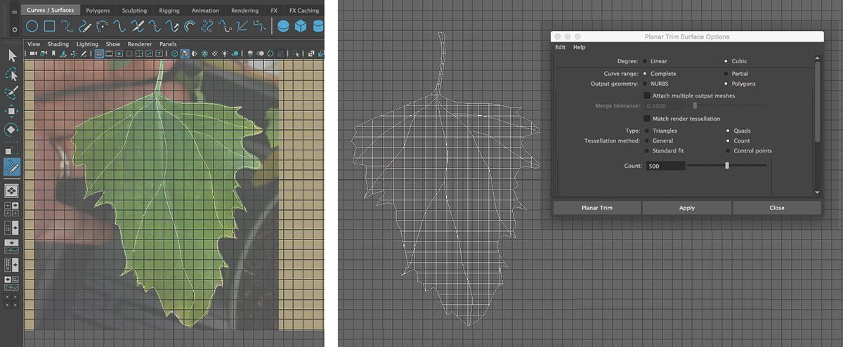
Figure 3: (a) The Pen Curve tool is used to create an outline and veins. (b) Convert the results to a "polygon planar". The conversion settings will join the edges and dice up the surface to make smooth bending of the polygon object possible.
9. Extrude the created planar to give volume to the leaf planar (Fig. 4).
10. Create a UV map using the top-view camera and export a render of the UV map (leaf_UV.png) for later use in creating a plant leaf texture. A UV map designates the position of images and other flat art on the models you are creating.
11. To bend the leaf shape, select one of the nonlinear deformers, “Bend” (Deform > Nonlinear > Bend) (Fig. 5).
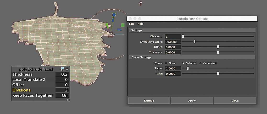
Figure 4: Extrude the two-dimensional (2D) planar leaf model into the third dimension.
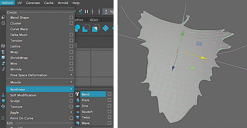
Figure 5: Use the "Bend" deformer controls (left) to shape the leaf model (right).
12. Soft select the leaf veins; move them down slightly to give depth on the leaf (Fig. 6).
13. Select the leaf and move the rotation/pivot location to the bottom of the leaf.
14. Duplicate the leaf and scale it down to make stipules and then position the resized leaf to the petiole of the original leaf by snapping.
15. While you do the snapping of the resized leaf objects, you also need to change the direction of the objects. Click the ‘e’ key and rotate the direction of the objects. After relocating each object, select all of the leaf objects and ‘Combine’ to make a single object.
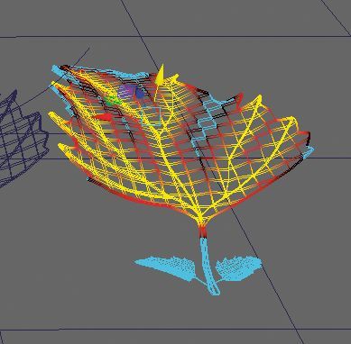
Figure 6: Soft selection allows movement of parts of the leaf to be effected less the further away it is from the selected veins.
We now have the basic leaf unit for duplication on the plant stem. Quinoa leaves have a similar construction at all sizes, so we have to make only one leaf.
Seed Modeling
1. Create a sphere and set the subdivision in width and height to 20 and 24, respectively. Subdivision allows a very simple shape to have a smoother appearance.
2.
Select and move the edges, and reduce the scale, to make the shape of a quinoa seed (Fig. 7).
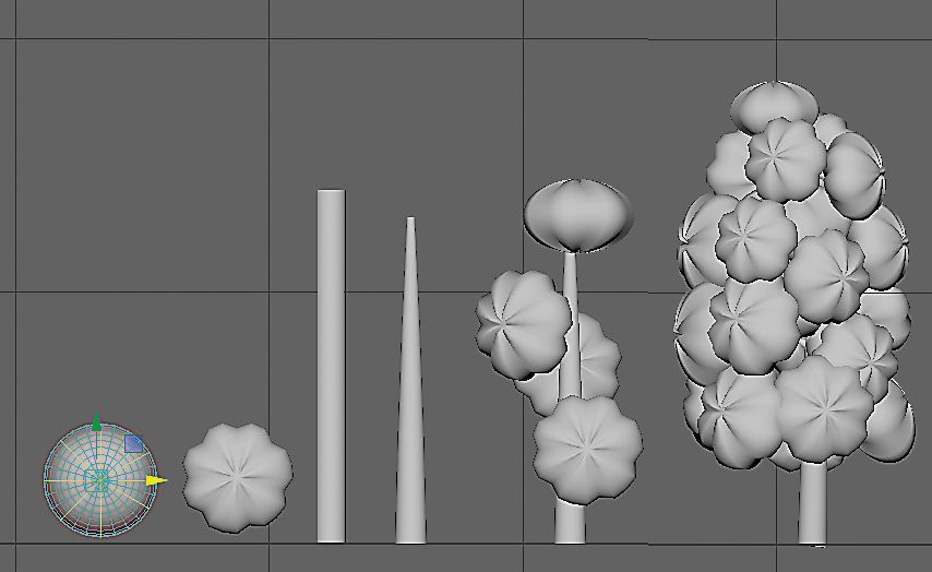
Figure 7: Seeds are modeled from spheres, multiplied and snapped to a stem tip model.
3. Create a UV map while viewing the top of the seed through the camera window.
4. Select the object and change the Y scale; then change the rotation/pivot location to the bottom of the seed.
5. Create a cylinder for a seed bunch stalk.
6. Duplicate the seed object and snap the duplicated seeds on to the cylinder to make a bunch.
7.
While you do the snapping of the seed objects on the cylinder, you also need to change the direction of the objects. Click the "e" key and rotate the direction of the objects. After relocating each object, select all of the seed objects and ‘Combine’ to make a single object.
Stem Modeling
1. Create a cylinder for the stem.
2. Soft select the vertex at the top and reduce the scale to create a tapered appearance (Fig. 8).
3.
To give a bowed appearance to the upper portion of the stem, use one of the nonlinear deformers, “Bend”. To give a twisted shape to the stem, use another of the nonlinear deformers, “Twist”.
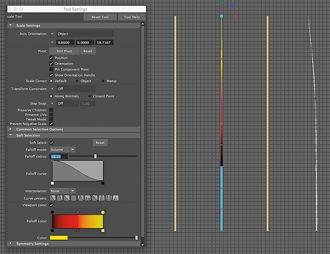
Figure 8: Soft select the end of the stem and reduce the diameter; then apply the Bend and Twist deformers to give the plant an asymetrical appearance.
Taproot Modeling
1. Select the curve drawing tool and draw a curve following the shape of the taproot through the front camera view.
2. Create a NURBS circle curve and snap the circle to the first control vertex of the taproot curve.
3. Select the taproot and circle curve in order; then open the extrude control box to create a tapered shape.
4. Select the root and change the rotation/pivot location to the top of the Taproot.
5. Duplicate the taproot and scale it down to make smaller branch roots and then attach the resized roots to the proper location of the original root by snapping.
6. While you do the snapping of the resized root objects on the taproot, you also need to change the direction of the objects. Click the "e" and rotate the direction of the objects. After relocating each object, select all of the root objects and "Combine" to make a single object.
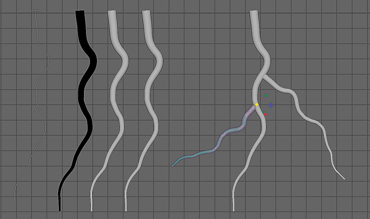
Figure 9: Create a taproot from a drawn curve and a circle primative extruded along the curve; then duplicate, resize and repostion root copies to expand the root system.
Add fibrous roots using the Paint Effect Tool. The Paint Effect Tool is a built-in method for creating many organic textures and shapes, such as plants, hair, fire, feathers, oil paints, pastels, and watercolors.
1. Create a polygon disc for the Paint Effect tool drawing.
2. Locate the disc at the bottom of the stem.
3. Set the disc to be paintable.
4. Click the "Get Brush" and choose a preset brush that is similar in shape to that of the fibrous roots.
5. Change the scale of the brush and draw a line on the disc.
6. Adjust the setting under the "Attribute Editor" to make it look like fibrous roots. A large number of adjustments are possible to create a customized result.
7. Convert a copy of the object from the paint effect to a polygon to make it renderable in the Arnold renderer (Modify > Convert > Paint Effects to Polygons) (Fig. 10).
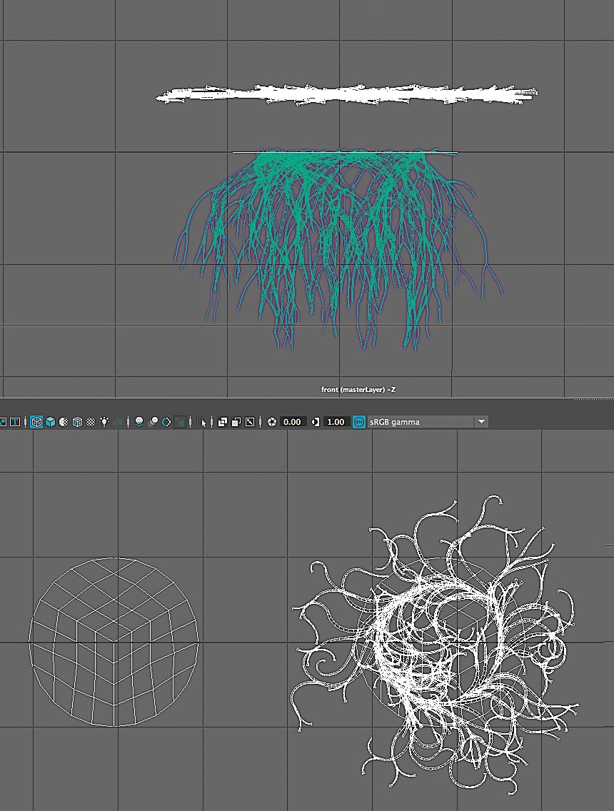
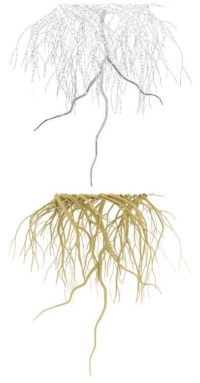
Figure 10: (a) Use the Paint Effects tools to create a fiberous, root-like objects attached to a disk. (b) Convert the object to a polygon object for rendering in the external Arnold renderer.
Assembling
1. Duplicate the combined leaf object and snap them into position on the stem following the real structure of the quinoa plant.
2.
Snap the seed head and root objects to the stem.
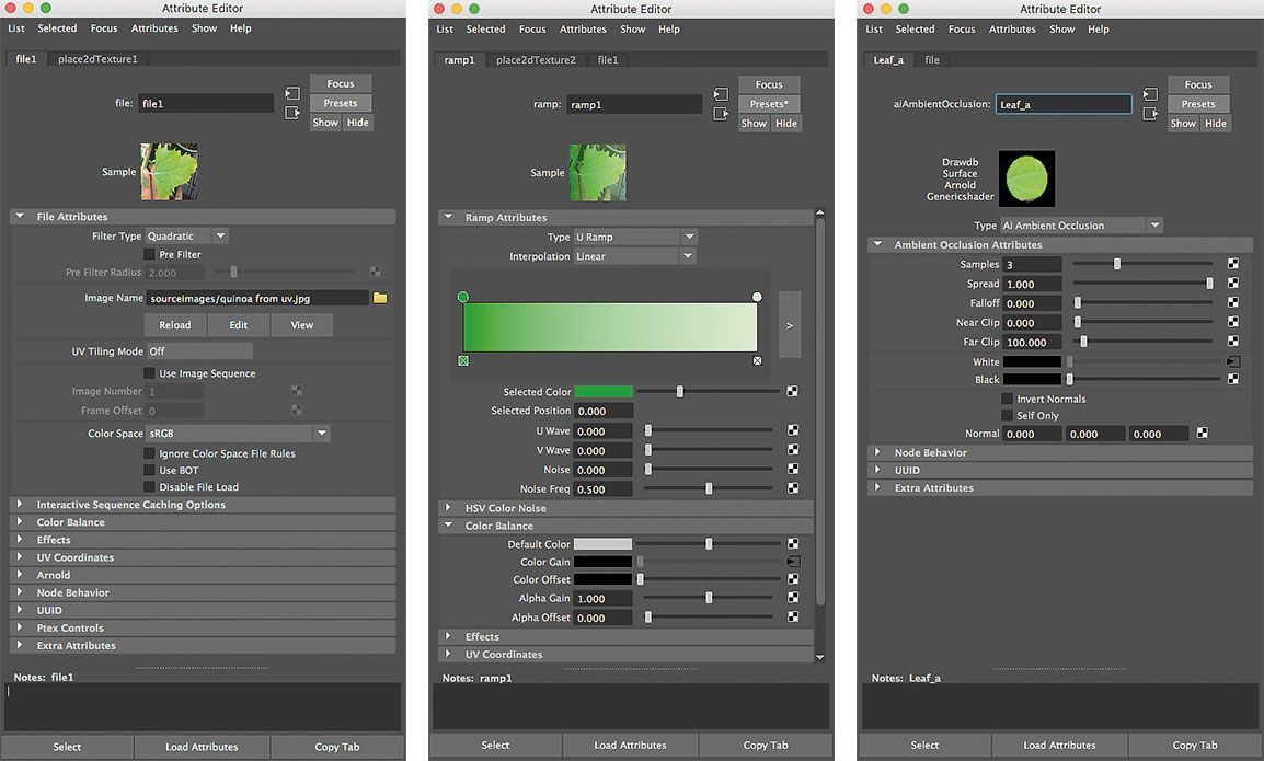
There are various texturing materials (shaders) in the “Hypershade” window. Choose a material depending on the surface texture desired for the object and the render engine to be used. In addition to using the image of the quinoa leaf for texture color, in this tutorial, I use the AmbientOcclusion shader for texturing. In particular, if the object does not have transparency and transillumination (also known as subsurface scattering), the AmbientOcclusion shader will make the rendering while creating realistic shadow/shading effects without creating a lighting setup when using the Arnold renderer.
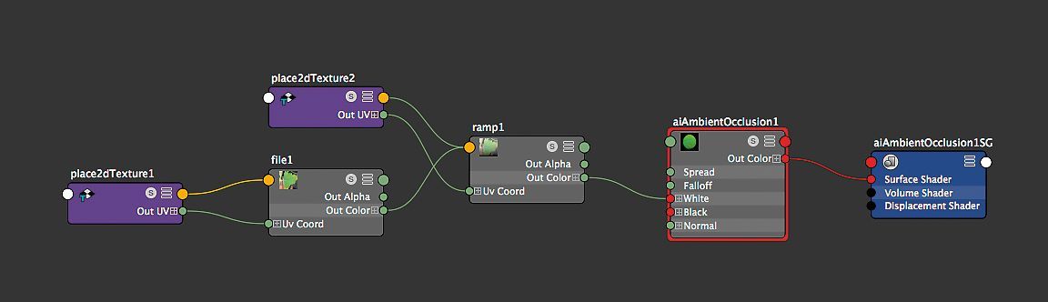
Figure 11: Shader tree: a sample shader showing how the different materials are processed into the final texture that is applied to an object, in this case an AmbientOcclusion type shader for the quinoa leaf.
Texturing
1. Switch to Photoshop and create a new doc- ument (2,048 × 2,048 pixels, 72 dpi).
2. Open the file leaf UV.png and layer the image from leaf_t.jpg on top.
3. Reduce the opacity of the leaf photo layer so that you can visually resize the photo to fit into the leaf UV area. The resized photo should be a little bigger than the leaf UV.
4. Increase the opacity of the photo layer back to 100% and then save the image as "leaf_Co" after flattening the image.
5. Switch back to Maya and open the Hypershade window.
6. Create an AmbientOcclusion shader for the leaf (with "ramp" for gradation on the leaf and "file" for image color on the leaf). Name it "leaf_A". Select the leaf object and apply "leaf_A".
7. Open the shader’s materials attribute and apply the "leaf_Co" image.
8. Create a second AmbientOcclusion shader (with another "ramp" for texturing of the seeds). Name it "seed_A". Select the seed bunch and apply "seed_A".
9. Create a third AmbientOcclusion shader (with another "ramp" and "grid" for texturing of the stem). Name it "stem_A". Select the stem and apply "stem_A".
10. Create a fourth AmbientOcclusion shader and rename it "root_A". Select all of the roots and apply "root_A".
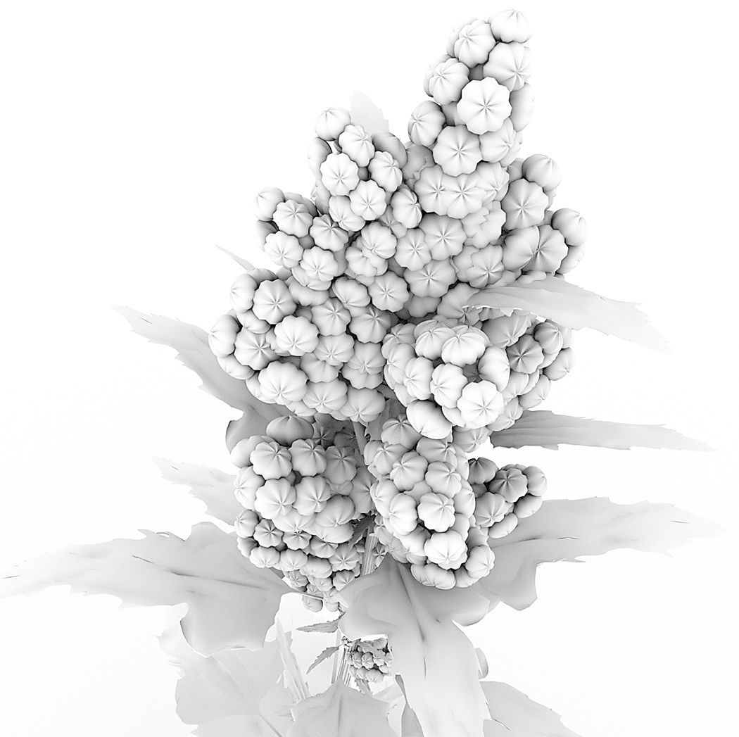
Figure 12: Ambient occlusion is a shading and rendering technique used to calculate how exposed each point in a scene is to ambient lighting (lighting that comes from all directions). The appear- ance achieved by ambient occlusion alone is similar to the way an object might appear on an overcast day.
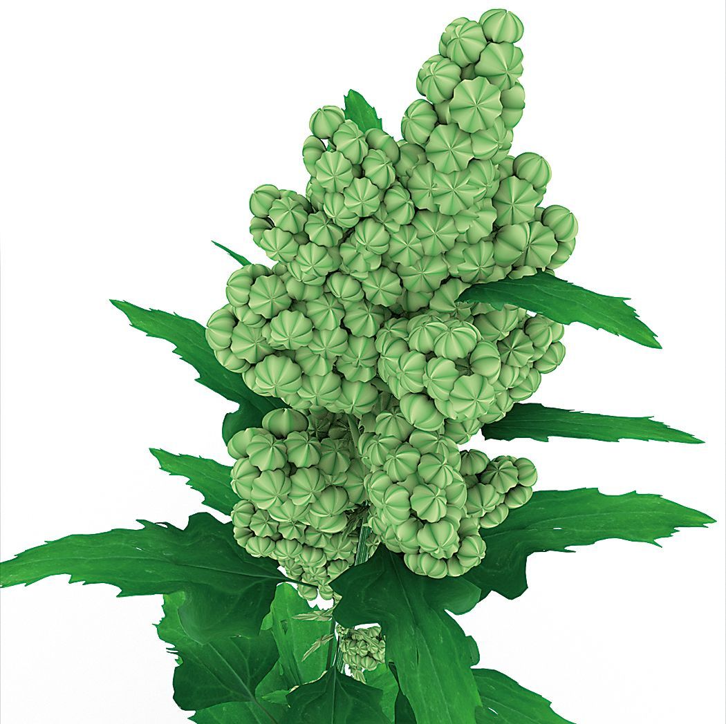
Figure 13: (a) Color texture can be added to shaders by importing images or (b–d): (below) generating graphics with internal tools in the shader’s attribute editor.
Rendering with Arnold
Maya has a built-in renderer, but other rendering software can be integrated that may have additional features or a better render apperance. One such renderer is called “Arnold”. We used it for this project.
1. Open the render setting and set up the image size and quality, for example: 1,080 × 1,920 pixels at 300dpi.
2. Create a camera and aim the focus on the quinoa plant.
3. Change the setup of the camera. Change the focal length from 35 to 200 and rearrange the location of the camera to focus on the object. The longer focal length minimizes image distortions.
4. Open the render setup window and launch the Arnold renderer.
5. After completion of the rendering, export the image and name it "quinoa plant_Co".
6. Create a new render layer and name it "AO"; then create a collection under the subdivision to add all of the objects.
7. Create a shade override and apply a new AmbientOcclusion to the collection. This will be for a shadow-only render.
8. Switch the active render layer to "AO" and complete the rendering.
9. After completion of the rendering, export the image and name it "quinoa plant_Oc".
The purpose of this second render is to have a separate, adjustable ambient occlusion shadow layer for compositing in Photoshop.
Compositing with Photoshop
1. Open the two rendered images "quinoa plant _ Co" (color image) and "quinoa plant _ Oc" (shadow image).
2. Place the "quinoa plant _ Oc" (shadow image) as a new layer in the "quinoa plant _ Co" (color image). Now you can experiment with different blending options.
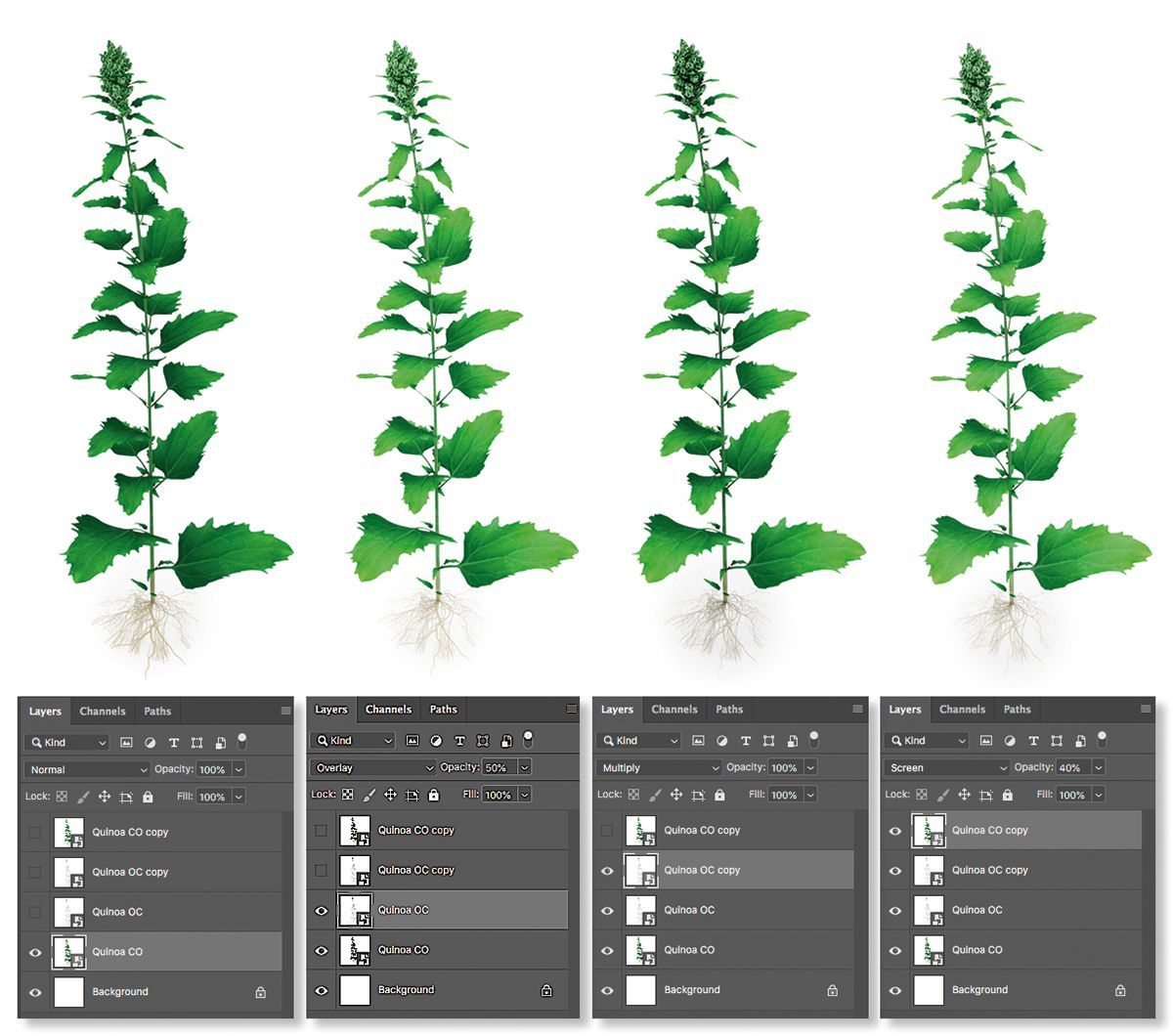
Figure 14: Two renders of the plant are made. One is the “color” version (quinoa plant_Co), the second is just the ambient occlusion shading (quinoa plant_Oc). These are then duplicated in layers inside Photoshop. By turning on different layers and adjusting the layer type and opacity, different “looks” can be quickly created for client approval.
HOW CAN I MAKE THAT?
When I receive a new illustration project, and while I am doing the brainstorming based on the request, I am already thinking about how I can build up each component structure in Maya. Even if it looks easy to build in the 3D space, I also have to imagine a rough way of texturing with lighting and any additional effects. After creating a simulation in my brain, to move forward, I open Maya and start test modeling and test texturing, focusing on a part of the illustration project. The testing result can be used for the draft version with additional sketches to seek the client’s agreement.
Unfortunately, working with Maya can be a time- consuming process. To have a high-quality detailed image, you may need to move vertexes or edges one by one for a long time to get just the right shape. However, I would like to say that although this is the usual process in working with Maya, it will be easier and faster with experience. The important thing in modeling is that the final 3D object should be easily retouchable for later additional modifications. In addition, the texturing should also be set up to ease modifications based on the client’s feedback. At the final stage of this project, the client asked me to increase the number of fibrous roots and to modify their direction to be more spread out. This change was easy to deal with through the Attribute editor of the fibrous roots.
The skills used in this tutorial are not special techniques and are close to the basic level of skills needed to begin modeling with Maya. If you are interested in using Maya, I hope that following this tutorial will provide a helpful path for understanding the workflow and some insight into how to use Maya.
This open-access article appears in the Journal of Natural Science Illustrators, Vol. 51, No. 1, 2019.

ABOUT THE AUTHOR
Heno Hwang is a Senior Scientific Illustrator at King Abdullah University of Science and Technology in Saudi Arabia. While he was studying microbiology (BA) and molecular medicine (MS), Heno discovered that developing an image for understanding the scientific logic of a project and transferring information was a powerful way to communicate science. Heno studied Maya VFX at the Aniaatus Design Academy, and Medical Art at Dundee University in Scotland. As a biomedical illustrator and animator, Heno creates scientific images and animations for research projects, scientific journals, presentations, and television.
Share this post: